The Job: Mechanical Modeling (Computer Aided Design)
Transportation, Industry and Consumer Products
A contempoary Design
Process should result in 2D requirements/drawings, and 3D computer models. These
2D and 3D files define each component and the product assemblies. 3D model files
(like STEP or IGES format) are needed in production for 3D Printing and other
Computer Numeric Control (CNC) machining. The computer models of a product can also
be used to simulate product manufacture and/or product use performances.
SIMULATE TWICE, MAKE ONCE.
In industry, 2D
drawings and requirements documents have always been necessary. The need for 3D Models has become much more
necessary over time. Like a picture worth 1,000 words, an accurate 3D model conveys
all possible dimensions. The supporting drawing need only display a dimension to verify scale,
along with key dimensioning and tolerances for performance.
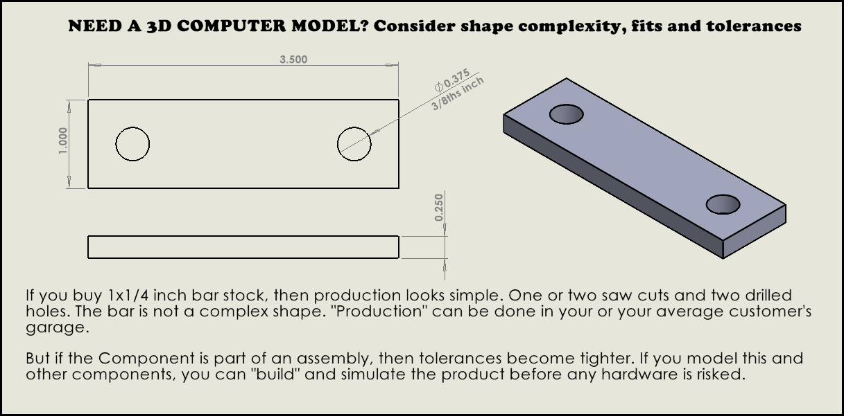
Simple shapes like the bar drawn above takes minutes to 3D model and
produce a 2D drawing to define basic dimensions. It is simple because it can be made at home, using hand tools. HOWEVER, if this
one part needs to fit in an assembly, then more requirements are added like
tolerances, and surface conditions. Product performance factors add other requirements,
like material strength and surface coating.
The growing prevalence
of CNC machining over the past few decades has made it easier to make
complex shapes that can save money, improve function, or improve product
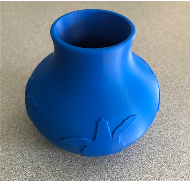
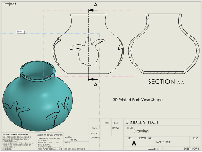
appearance. The Turtle Vase below is a curved shape with this company’s logo
embossed on the perimeter. This was an easy
make for a 3D printer (see blue pictured below). This product would be very difficult to
machine outright without 3D printing, but if a mold or cast is machined in a first step then it
could be made by blowing plastic or glass.
The design is
adapted to the chosen method of manufacture, is it formed, molded or machined?
Different methods place different requirements on a Part’s design, like
allowances in sheet metal or draft angles in molds.
In a production
ramp-up, any given Part may initially be produced by one method, and then
redesigned for a second method. A method like machining can have lower capital tooling cost with
a higher per piece cost. A method like molding would have lower per piece cost, but
the mold is a higher capital cost. A Part might be machined initially allowing
sales to justify a change to molding.
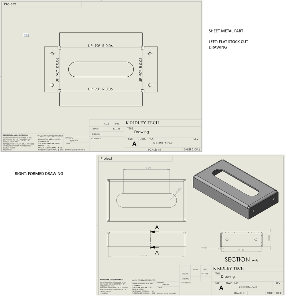
Solid Modeling is
useful to support the different steps of component manufacture, like the formed
box shaped below. The “flat” could be laser cut, the second drawing
is for the Part when formed.
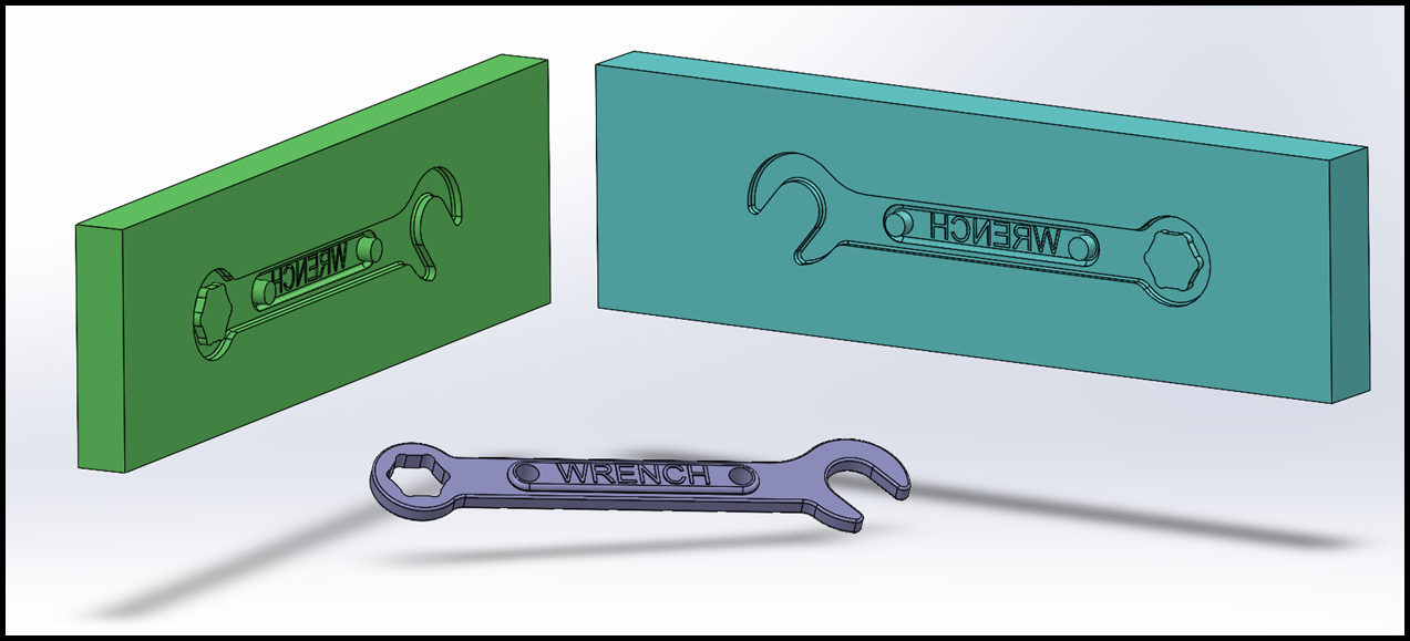
Then there is
casting or molding, the mold (the negative shape) can be quickly modeled from
the Part’s 3D model. Then mold halves can be scaled up to account for predictable
shrinkage as a molded part cools.
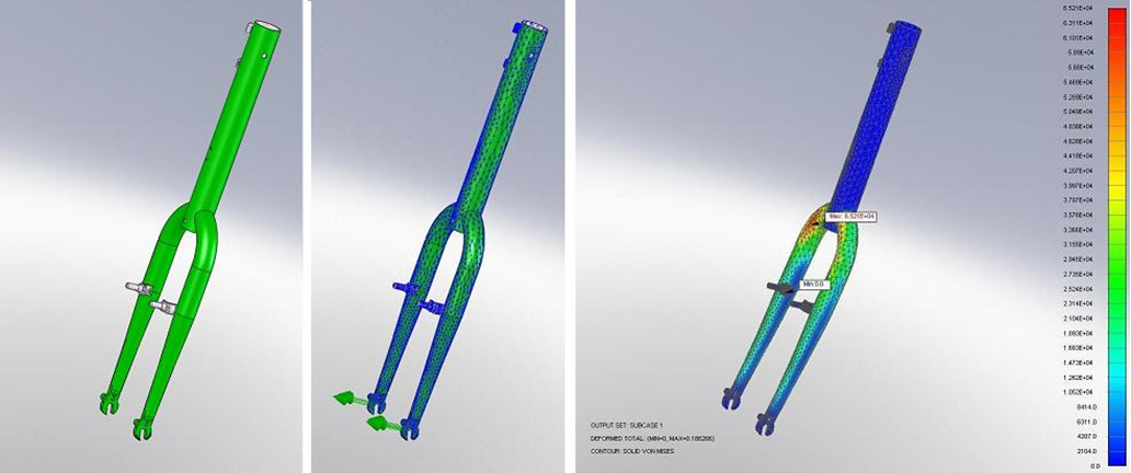
The Finite Element
Stress test below is an example of virtual strength test of bicycle fork. CAD models and simulations reduce risk, they do not eliminate all risk. Something can pass a CAD simulation and
still fail for other reasons. But, if something fails in a CAD simulation, it
will also fail in product testing. The CAD simulation is a much cheaper way to
learn.